Rework of 3D printed parts
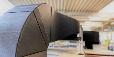
Housing made of PA CF | FFF process | Application: Automation
Our processes for the reworking of 3D-printed plastic components
In principle, additively manufactured components can be used without further processing steps. However, additively manufactured components can be optimized for certain applications. Particularly for technical applications, special processes can be used to get the maximum out of a 3D printed component.
The following goals are pursued:
Increase accuracy
Optimize optical properties
Due to the production process, printed components have a relatively rough surface as a result of the layer structure. For special applications, the surface can be optimized by certain 3D printing finishing processes. Various process steps are used to smooth and deburr 3D printed components and to eliminate small process-related defects.
Possible processes:
- CNC milling
- grinding & polishing
- vibratory grinding
- blasting
- local melting
- chemical smoothing
Reinforce components
Various post-treatment processes strengthen 3D printed parts in terms of strength and durability. Due to the layer structure, the strength in the layer direction of 3D printed parts is somewhat reduced. This effect can be counteracted by various processes.
Possible processes:
- chemical post-treatment
- annealing
- hot powder compression
Extend functions
The functions of 3D printed components can be extended by various processes or assembly steps:
Possible processes:
- joining by e.g. bonding
- assembly of further construction elements
- functional coatings

Pinning and bonding of partial segments of a housing cover made of rPETG | FFF process | Application: automation
The rework processes in detail
3D Printing Rework by CNC Turning and Milling
In contrast to additive manufacturing, CNC milling and turning are subtractive processes and achieve significantly higher accuracy. However, much more complex geometries can be produced using 3D printing. When both manufacturing approaches are combined, components with unbeatable properties are created.
Most components, whether additively manufactured or conventionally, require special tolerances only in certain areas. These are precisely the areas that are reworked using machining processes, which is already taken into account during printing. Areas printed with allowance are specifically machined, for example to achieve flange surfaces with exact flatness and low roughness. Threads or fits are turned and milled in order to mount further components.
For technical components with special tolerances, we therefore recommend that you always send us a drawing with the tolerances in addition to the 3D data and describe the intended use with important general conditions. With the additional information we analyze which manufacturing steps are necessary to achieve the optimal result.
The linking of additive manufacturing and conventional machining has long been state of the art at Hänssler, because we have always combined both worlds and fully exploit the respective advantages. Both production areas are linked to each other, which allows us to coordinate all manufacturing steps and respond highly flexibly to customer requirements. Due to the different production areas at one location, we realize short and binding delivery times even with several production steps.
3D printing surface smoothing by grinding and polishing
Grinding and polishing of printed plastic parts is one of the most common methods to improve surfaces, remove defects or round edges. Large-scale grinding should be avoided by optimizing the printing process to reduce time-consuming manual work as much as possible. For some applications, however, it is unavoidable, especially if subsequent coating processes are planned. Manual grinding and polishing is only suitable for large-area geometries. It is not recommended for filigree components, since not all hard-to-reach areas can be reached with conventional tools. Particularly harder plastics such as PETG, PC and PPS can be ground better than soft plastics.

Reduce surface unevenness by local melting
We use this process very often for 3D printed parts, as small threads can occur during the process path in 3D printing due to the manufacturing process. A hot air gun is used to briefly apply hot air to the additively manufactured component. This causes the small threads to melt together and remain as small drops on the surface. These drops are subsequently wiped off or removed with a deburring tool. Since the impact hits the component only for a very short time, the main structure is not affected. Hot air can also alleviate the marks after grinding processes on dark components and produce a homogeneous surface appearance.

Deburring and smoothing of 3D printed parts with particle beams
In general, this process is often referred to as sandblasting, although in most cases no sand is used, but various blasting media. We often use special granules made of plastic for gentle removal. The manual process is laborious and can be a good choice especially for filigree geometries. Inner channels or angled structures are difficult to reach with the abrasive and the effectiveness of this method must first be evaluated for each component.
Partially automated vibratory grinding of 3D printed parts
If particularly uniform surfaces are required for optical or functional reasons (e.g. channels for media), vibratory grinding is used for some suitable plastics. In special rotating or vibrating systems, the component and abrasive particles are set in motion together with water. The abrasive particles remove the component evenly, the surface is improved and edges are broken. Not all plastics are suitable for vibratory or barrel finishing; they must have a certain hardness. If the plastics are too soft, no stock removal will occur. For larger quantities, vibratory finishing, sometimes also called tovalizing, is particularly effective because it is largely automated.
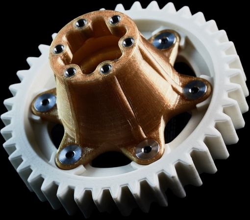
Drive unit made of ULTEM™ 1010 and iglidur® I180-PF | FFF process | Application: Plant construction
Chemical smoothing of 3D printed parts
If particularly high-quality surfaces are required, chemical smoothing processes can be the solution. Particularly for complex geometries, when other methods fail, these processes are a target-oriented alternative. In an industrial context, the printed components are exposed to an acid mist and the acid is neutralized again after several cycles so that no harmful substances are produced. However, this method only works with the plastics PA6, PA11, PA12, TPU, PLA, PET and PMMA.
The smoothing in this process also causes an increase in strength by reducing the notch effect between the layers.
We cannot recommend processes known from the hobby sector where acetone is used. The components are too damaged and become brittle, and the process is a risk to health and the environment.
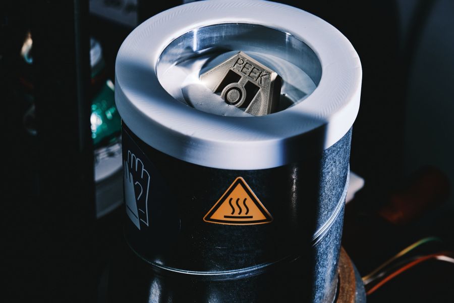
Tempering of 3D printed plastic parts
In most printing processes, plastic is melted and re-solidified by simple cooling. Particularly in the fusion layer process (FFF or FDM), this results in amorphous molecular structures. This means that the molecules remain largely disordered, thus reducing the possible strength of the plastic part. The process-related uneven cooling additionally generates residual stresses in the component. To eliminate stress and convert amorphous molecular structures into semi-crystalline structures, certain plastic parts are subsequently heated up to the glass transition temperature. The annealing curves are defined depending on the plastic and the wall thickness. Temperatures are maintained for specific periods of time and then slowly cooled once the effect has been achieved. Tempering can thus improve mechanical properties and reduce residual stresses in the component. We recommend an annealing process especially for components that are subjected to thermal stresses during use, so that the residual stresses are not released during use and lead to unwanted distortion.
We also specifically apply the annealing of plastic parts or their semi-finished products in our machining production areas. Due to the mostly extruded semi-finished products, the same problem exists and can be counteracted by tempering.
Assembly of other construction elements
The function of 3D printed components can be extended by mounting additional elements. These include, for example, threaded inserts, screw connections, but also electronic components. Especially the use of thread inserts is recommended for many applications. Small threads cannot be directly mapped in the additive or do not bring the desired strength in the plastic. Therefore, the holes are matched to special thread inserts made of stainless steel, for example, and mounted after printing. Due to the thread inserts, high strengths are realized and the thread can be used several times.
For special applications, components can also be inserted and completely enclosed during printing. For this purpose, pauses are defined in the program code at the exact position where components are inserted. Afterwards, the print is continued and receives unique integrated functions.
3D printed parts with functional coatings
In electrical engineering, plastic parts are often used to benefit from the isolating properties. However, this also results in disadvantages, for example with regard to shielding properties. Unlike metal housings, plastics provide only limited shielding against electromagnetic radiation. If metals cannot be used due to electrical conductivity or lightweight construction requirements, special EMV coatings are a solution. In this process, the printed component is pre-treated and coated with special varnishes on defined surfaces. This coating protects the internal electronics from electromagnetic radiation in the assembled state.

Hot powder compression of additively manufactured components
The process-related layer structure in 3D printing has known disadvantages. In particular, the lower strength in the layer direction compared to conventionally manufactured plastic parts can lead to limitations in some applications. In addition, the layered structure often creates pores or blowholes and can lead to leaks in media-carrying components.
In a research project, we have demonstrated that 3D printed components can be redensified using a special process. In this process, the components are heated in a special powder bed and re-sintered at high pressure under mold constraint. The result is pore-free components in which the individual layers are firmly bonded together. This process is still under development, but can be used for small components on a test rig.
3D printing components joining by bonding and pinning
As with conventional manufacturing, available processing space on the respective machines limits the size of the component. Although certain materials can be processed in large-format printers, for certain applications it is necessary and also makes economic sense to join smaller sub-segments to form the final component. For exact alignment, holes for positioning pins are planned in advance in the 3D data set, which are mounted after printing. Suitability for bonding varies for each plastic and must be evaluated on a case-by-case basis. The adhesive and also the preparation must be precisely matched to the material. If necessary, the joining surfaces are pretreated, coated with adhesive and joined in the correct position with the aid of locating pins. With the right material pairing, high-strength bonds can be produced depending on the material. When selecting the adhesive, the media with which the component comes into contact must also be considered.
Get free advice now!
Our 3D printing professionals look forward to hearing from you. Together, you will talk about the individual challenges and find economical solutions for the post-processing of your 3D printed components.
Arrange your non-binding initial meeting today.
