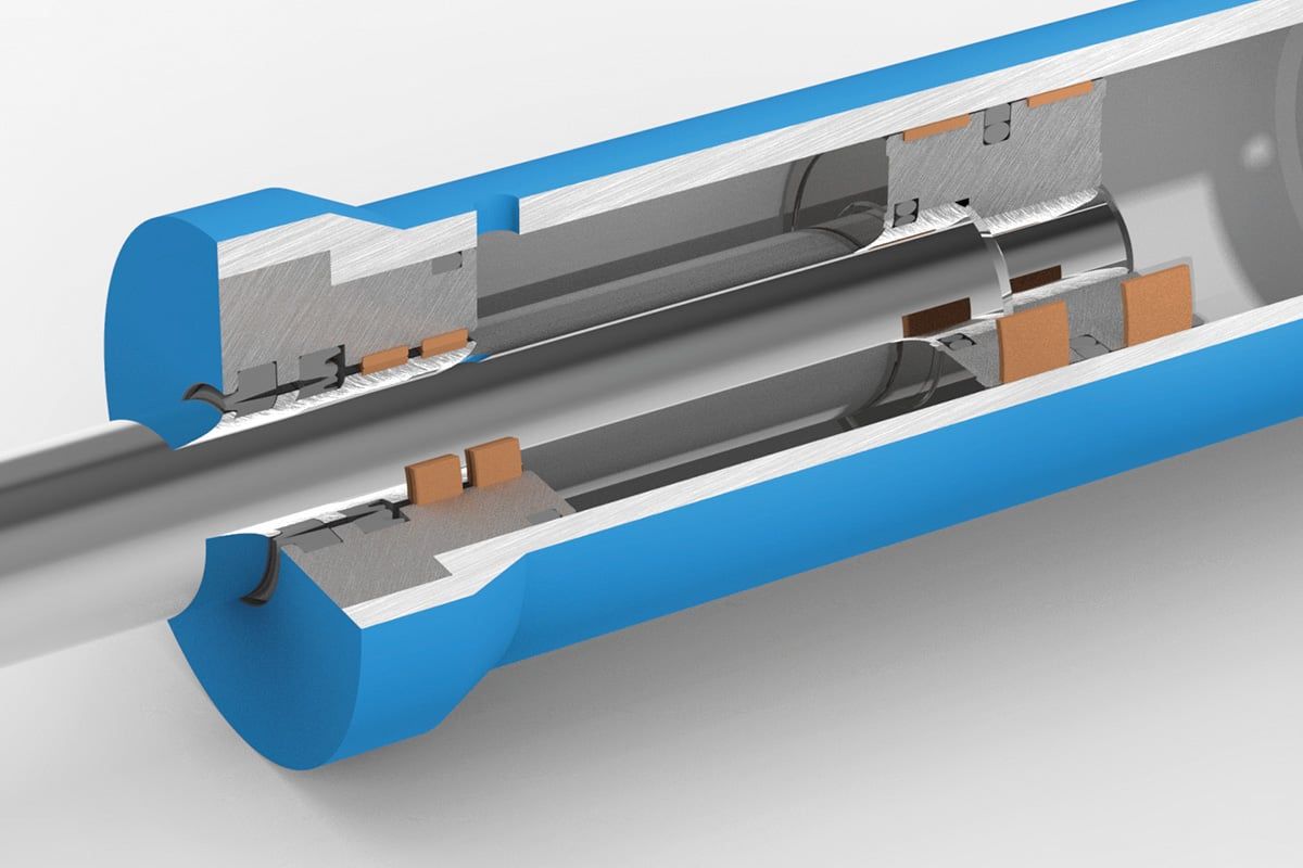
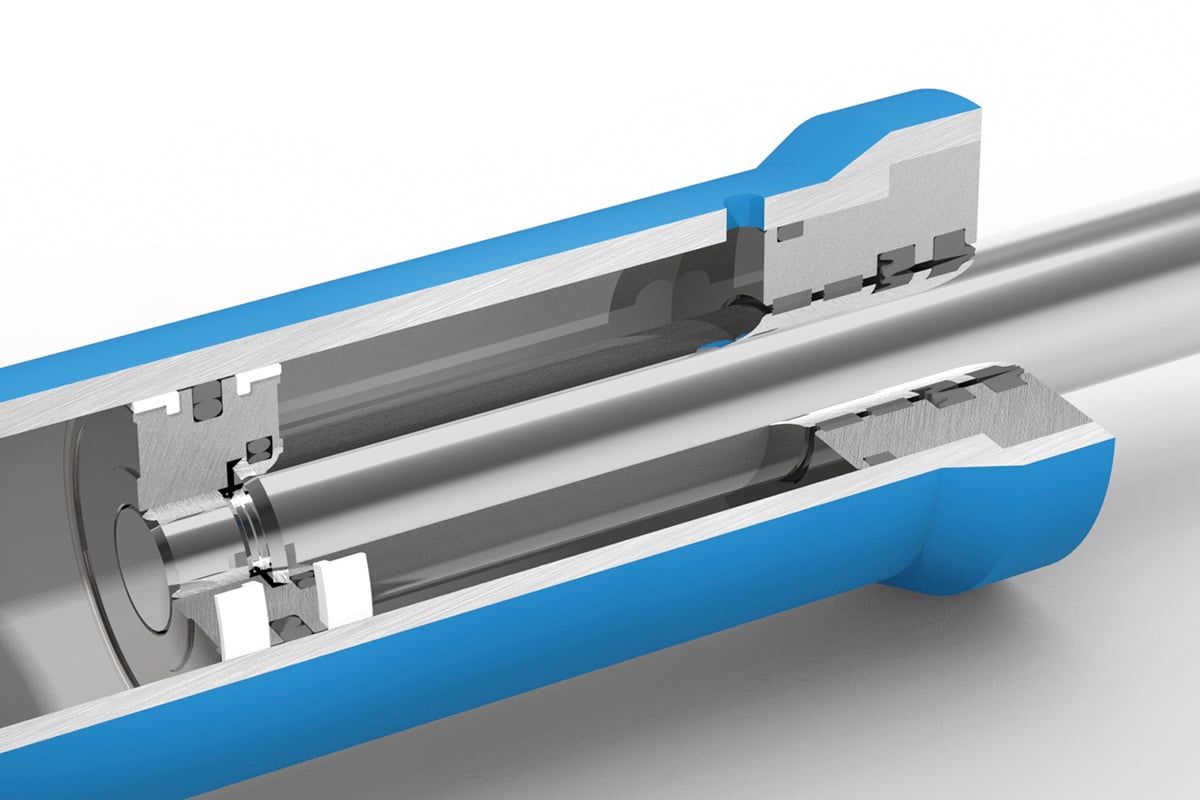
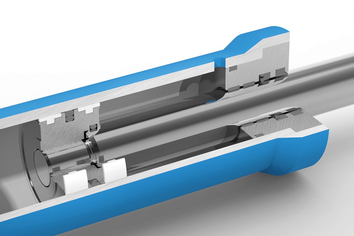
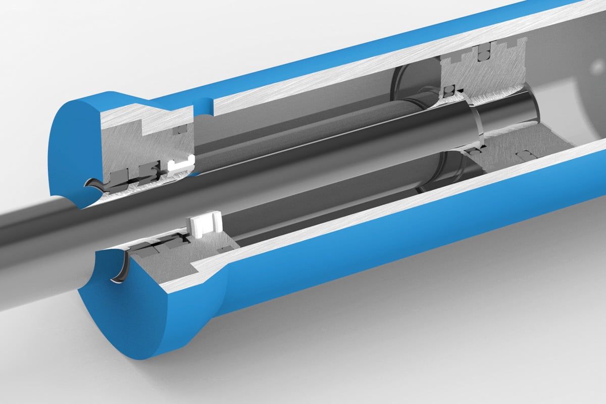
Piston and rod guide rings absorb transverse forces and avoid metallic contact between the sliding components. The additional element separates the “sealing” and “guiding” functions. In contrast to metallic guides, guide rings made of plastics are a cost-effective solution, reduce friction and wear, and in many cases do not require lubrication.
Standard profiles
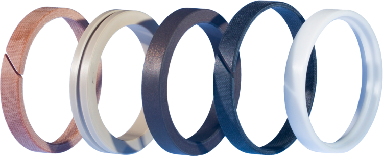
By the standard profiles shown, we mean guide rings that represent the state of the art. We manufacture these guide rings ourselves for all required groove dimensions from a variety of materials. In addition to turned and injection-molded guide rings, we supply many dimensions as yard goods or ready-cut.
For a general overview and more information, see the following categories:
Rectangular shaped guide rings
L-shaped guide rings
T-shaped guide rings
U-shaped guide rings
Choosing the correct profile
The more information is known, the better a guide element can be adapted to a specific application.
To choose the right profile and the optimal material, the following criteria are important:
installation space
lateral forces
temperature range
medium
rotary / swivel speed
counter surface
installation option
friction behaviour
service life expectancy
price
availability
Rectangular shaped guide rings
Application
standard
cost-effective
also available by the metre or pre-cut
low friction
easy assembly in closed grooves
high loads
also available with step cutting
Brief description of the designations:
FR = Guide ring K = Piston S = rod
LN = Linear groove MN = center groove SN = Spiral groove
A guide ring is a guide element in hydraulic or pneumatic cylinders. It absorbs transverse forces, guides the moving components and prevents direct contact between the sliding components.
Plastic guide rings usually offer lower friction and less wear and, depending on the material, often work with little or no lubrication. In addition, they are often inexpensive and available in many profiles.
Piston guide rings are located on the piston and guide it in the cylinder tube; rod guide rings are located in the head/guide area and guide the piston rod. Both absorb transverse forces and prevent metal contact. They differ primarily in terms of their installation location and thus their installation space/groove dimensions and mounting design.
Guide rings can be requested from Hänssler Kunststoff- und Dichtungstechnik via the contact form, by phone, or by email. In addition to standard profiles, Hänssler specializes in manufacturing custom profiles and can use high-performance plastics for demanding applications.